Pt. 1 The theoretical basis
Probably one of the most important concepts in Structural Geology is the concept of stress and strain. I mean; somehow you have to explain all these wonderful structures that one can see in the field, right? The explanation is done with that concept, so: let’s get started, shall we?
What is stress and strain anyway? Well, what is an analogue in real life if you have to deal with a lot of stress? Maybe something like that you have been under a lot of pressure recently? That is actually more or less everything, what stress is; stress is a directional force (meaning this force always has a direction and can therefore be displayed with a vector). Strain on the other hand is the actual deformation of a rock, that’s the stuff we see in the field.
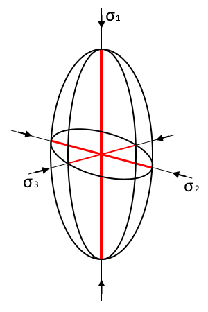
For purposes of convenience stress and strain are always applied in orthogonal, cartesian coordinate systems (therefor stress vectors on these axes are called principal stress vectors). That means that if a rock experiences deformation, there are always three force components working on that rock. The symbol for stress is the Greek letter σ. Per definition is given:
σ1 –> principal leading stress (direction of maximum stress)
σ2 –> intermediate principal stress
σ3 –> least principal stress axis (direction of minimal stress).
As a result, if we visualise stress as vectors, σ1 will always be the longest vector. In most cases however geologists don’t visualise vectors in a coordinate system but instead view stress in a stress ellipsoid (see Fig. 1).
Stress acting on a rock unit results in strain. If strain actually occurs (meaning rock is deformed), three types of strain must be distinguished: Translation, Rotation, Distortion, Dilation. You can see the different types of strain in Fig. 2.
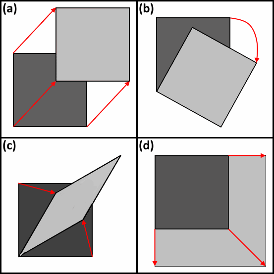
(a) Translation
(b) Rotation
(c) Distortion
(d) Dilation
One thing to keep in mind however is that in nature we can see multiple types of strain of strain superimposing onto each other. So, how do we visualise strain then? Ironically, we use an ellipsoid for that too, now it’s the strain ellipsoid. The theory behind this is that we take a completely spherical grain of any mineral and then apply stress to that mineral. As a result, the mineral will show strain, meaning it will deform. Now take a look at Fig. 3.
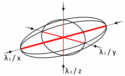
You will see that the strain ellipsoid is similar to the stress ellipsoid. The seemingly only difference is the different labelling of the axes, right? Right?? NO! Take a closer look! The formerly longest axis in the stress ellipsoid was the vertical axis, right? Now, in the strain ellipsoid this axis is the shortest one. Therefore, we can infer that the stronger the stress in a given direction is, the stronger the deformation [strain] will be in this direction. As for labelling there are two variants; x, y, and z, as well as λ1-3. As already alluded to, now by definition is given:
x or λ1 –> maximum direction of extension
y or λ2 –> intermediate strain axis
z or λ3 –> maximum direction of shortening
The different ratios of the axes to each other result in different shapes that an object can take. The resulting forms can be categorised in the Flynn-Diagram.
Keep in mind is that the overall orientation of the stress- and strain regime can change over time. Therefor we call all the structures that we see in the field the product of finite strain and the development of these structures is determined by the so-called incremental strain. The former is like a summation of all the strain events over a long time, while the latter gives an insight into the development of the researched structure at a given point in time.
With that knowledge, we can now establish the different strain regimes. You see, the finite strain (and therefor the finite strain ellipsoid [FSE]) does not give us any indication about the strain history. Therefor two endmembers of the strain regime were “invented”, in order to explain the resulting structures that we can assign our FSE to: pure shear and simple shear (see Fig. 4).
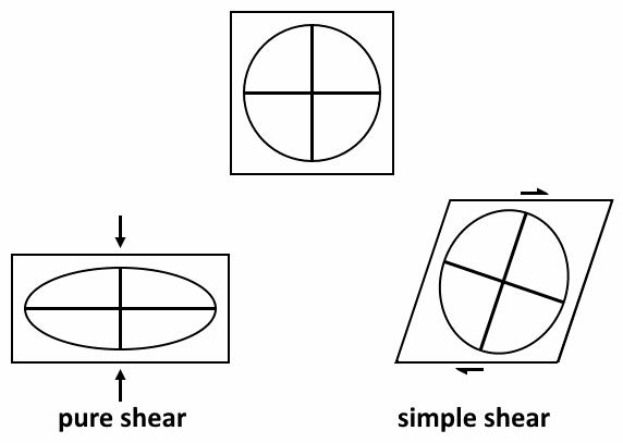
pure shear: Note that the grain is symmetrical in relation to horizontal and vertical symmetry axes
simple shear: Note that the grain is asymmetrical in relation to horizontal and vertical symmetry axes
In the case of pure shear, the axes of the FSE do not rotate during deformation, the axes of the FSE stay parallel to any incremental strain ellipsoid. In the case of simple shear however, the axes will rotate. If the both types are combined (most often the case), one uses the term general shear.
So; why do we need all of that? Well, with that knowledge we can now go to more practical examples and try to explain structures in the real world. For that see Part 2 (coming soon).
